Vortex Generator Effect, Shell and Tube Heat Exchanger, ANSYS Fluent
۳۶۰,۰۰۰ تومان تخفیف دانشجویی
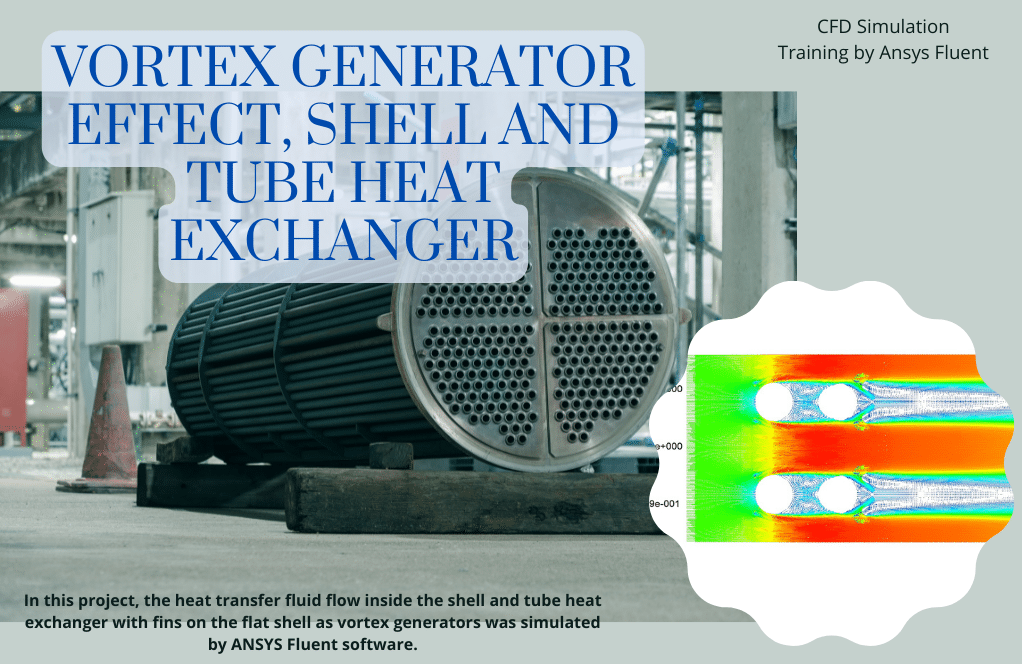
In this project, the heat transfer fluid flow inside the shell and tube heat exchanger with fins on the flat shell as vortex generators was simulated by ANSYS Fluent software.
This product includes Geometry & Mesh file and a comprehensive Training Movie.
There are some free products to check our service quality.
To order your ANSYS Fluent project (CFD simulation and training), contact our experts via [email protected], online support, or WhatsApp.
بر روی افزودن به سبد خرید کلید کرده و فایل های هندسه، مش و فیلم آموزشی جامع را دریافت کنید.
برای سفارش پروژه خود و یا بهره مندی از مشاوره رایگان، با کارشناسان ما از طریق ایمیل ([email protected])، پشتیبانی آنلاین و یا واتس اپ (09126238673) در ارتباط باشید.
برای کنترل کیفیت خدمات ما میتوانید از محصولات رایگان استفاده کنید.
توضیحات
Introduction & Project Description (Vortex Generator Effect on Shell and Tube Heat Exchanger)
The heat transfer from one fluid to another is done by a device called a compact heat exchanger. These types of heat exchangers cause heat transfer and have less volume and weight than other cases. However, they have some problems. For example, the fluid pressure drop in it, is more significant than the conventional exchanger. These types of heat exchangers are used in applications that require high heat transfer rates in limited volumes using vortex generator.
The compact heat exchangers are made in the different shell and tube heat exchangers, air-cooled heat exchangers, screw heat exchangers, spiral heat exchangers, plate heat exchanger type, and vertical and horizontal designs. This device is widely used in various applications.
Introduction & Project Description
various strategies to improve the heat transfer rate are used, the most important of which are:
- Adding fins in different shapes to increase the level of heat transfer
- Use facilities to increase turbulent flow in the fluid, such as adding baffle plates at a calculated distance
- The use of new materials such as sponge metals, polymers, and ....
Introduction & Project Description
The finned heat exchanger and other flow parameters such as fluid velocity, how the fluid enters and exits and moves, etc., are the factors affecting the turbulent flow. A useful strategy has emerged to increase heat transfer performance on the air-side using flow control, known as a vortex generator, in recent years. The vortex generator is a small protrusion on the surface that disrupts the flow regime and disrupts its boundary layer. When the fluid flow passes through the vortex generator, due to the separation of the flow at the edge of the vortex generator, vortices are produced in the direction of flow in the flow field, which causes mixing in the central part of the flow and changes in the boundary layer and its instability. Vortices are divided into transverse vortices and longitudinal vortices according to the direction of the vortex eruption.
Heat transfer increases due to these vortices. Vortex generators is a passive method to improve heat transfer. This method is commonly used to design compact heat exchangers. The most important factors influencing the vortex generator fin’s heat transfer performance are the vortex generator angle of attack, the generator’s length, and height. The heat transfer performance from surfaces with a vortex generator is susceptible to these two factors, especially its attack angle.
Introduction & Project Description
The contribution of the vortex generator to heat transfer from the surface is very small, and this improvement in heat transfer can be attributed mainly to the vortices created in the direction of flow and the correction of the separation area behind the pipes due to the vortex generator position relative to the pipes. Vortices increase the mixing and modification of the boundary layer, decreasing the air’s thermal resistance and increasing heat transfer. In passive methods, the increase in heat transfer is accompanied by an increase in pressure drop. The gradual pressure drop is mainly due to the formation of the perception caused by the vortex generator. In general, the production of vortices is the reason for the additional drag that occurs in the pressure drop.
In this project, we simulate the heat transfer fluid flow inside the shell and tube heat exchanger with fins on the flat shell as vortex generators by ANSYS Fluent software.
Shell and Tube Heat Exchanger Geometry and mesh
We model this project’s geometry in ANSYS Design Modeler software, and carry out its mesh by ANSYS Mashing software.
The following Figures show the geometry and mesh. As we can see in the Figure, the grid has two ways of structured in the side parts and unstructured in the middle part of the geometry. Also, The total number of mesh cells is 426100.
Vortex Generator Effect on Shell and Tube Heat Exchanger Numerical Setup for CFD Simulation:
In this simulation, we consider the following assumptions:
- Due to incompressibility, we implement the pressure-base solver.
- We perform this simulation as a steady-state.
- Due to the small effect of gravity, we neglect the gravity acceleration effect.
Due to the geometry’s symmetry and to reduce the computational cost, we model only a half of the geometry, and we also use the symmetry boundary condition.
We present a complete information on boundary conditions in Table 1 and following Figure.
Table 1. Table of Boundary conditions
| Inlet | 1.42 m/s & Normal to Boundary
Turbulence intensity: 8.023% Hydraulic diameter(m): 0.00257 Temperature(k) : 303 |
| Outlet | Pressure outlet |
| Symmetry | Symmetry |
| VG | Stationary wall |
| Tube | Stationary wall
Temperature (k): 338 |
We apply a Simple algorithmic the pressure-velocity coupling, and we choose SST model as a turbulence model. Also, we present the other settings such as the discretization method and initial conditions in the table below.
Table 2. Table of other numerical setups
| discretization |
|
||
| Initialization method | Hybrid |
Results & Discussions
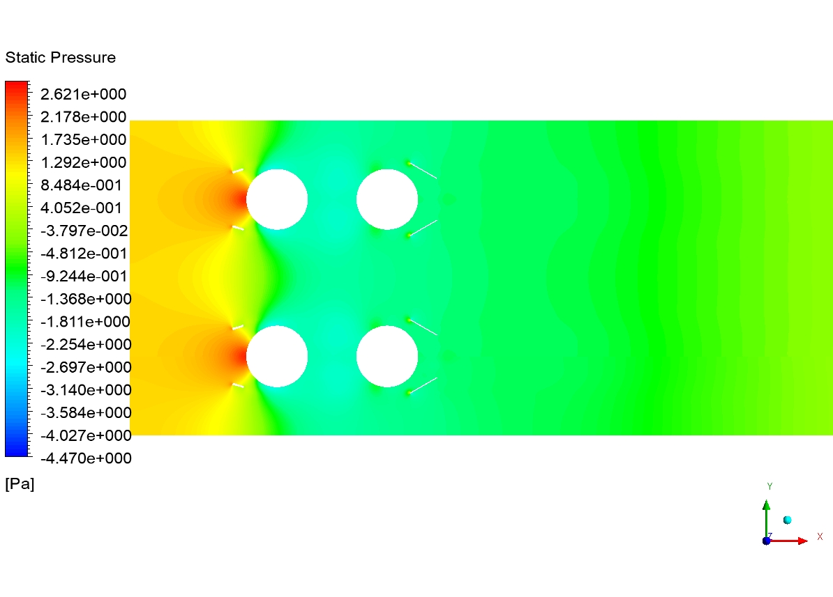
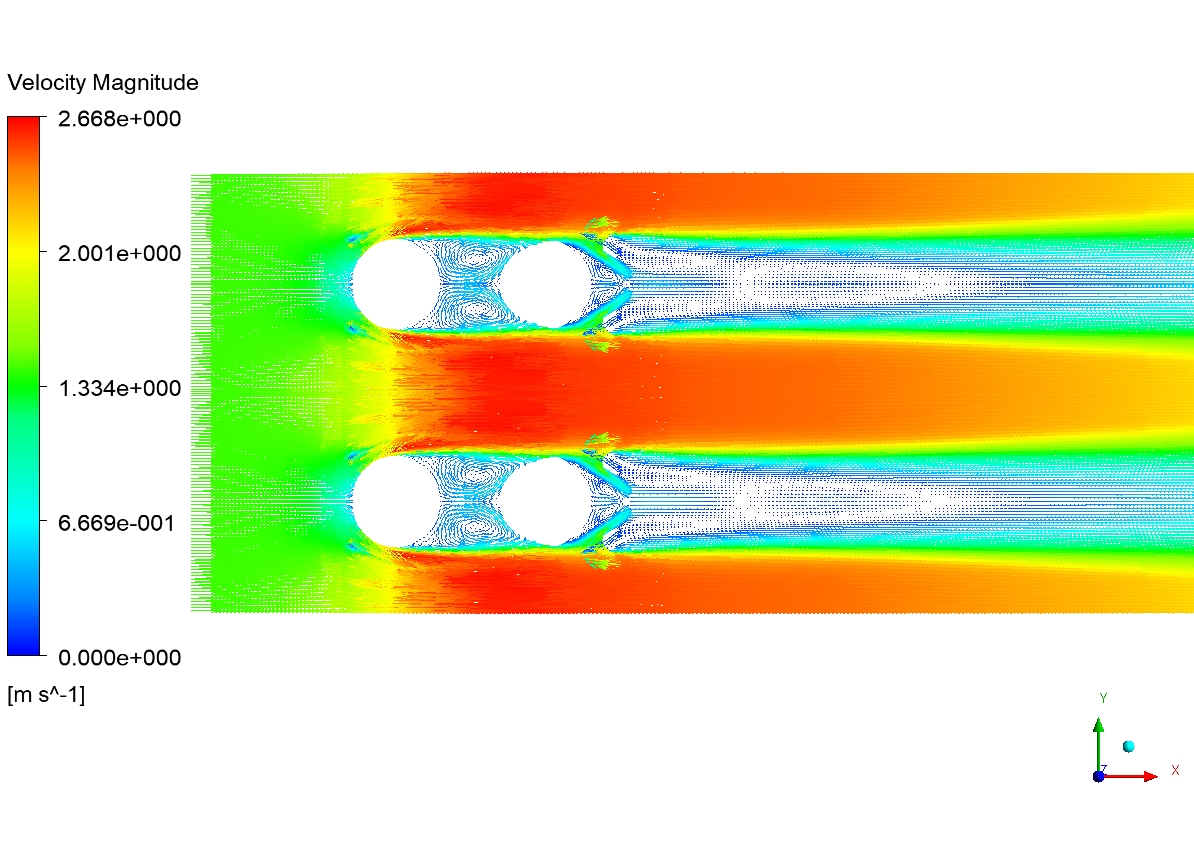
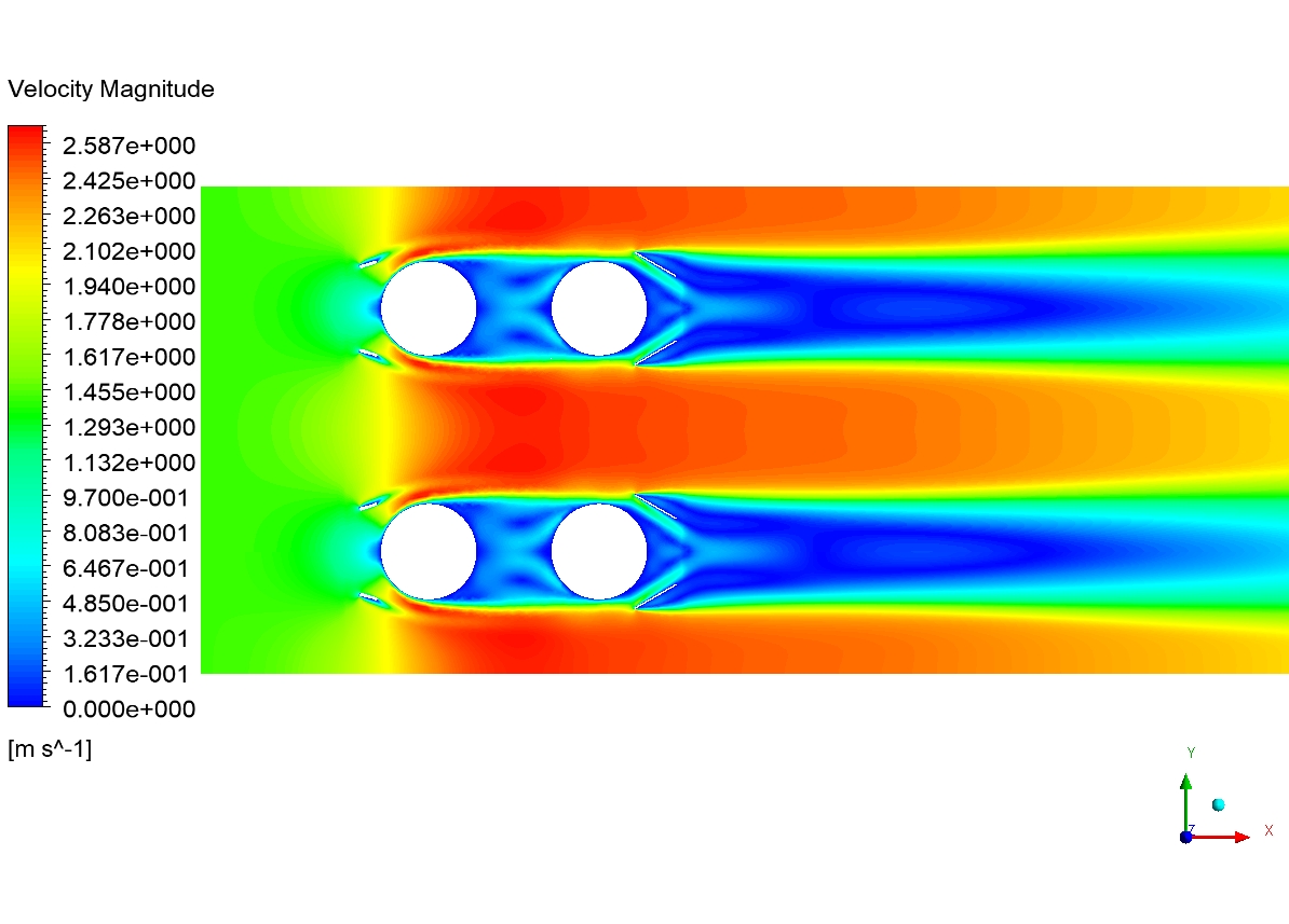
Although the tutorial video fully explains how to extract the results, In this section, as in the last section, we present contours of pressure, temperature, velocity, and vectors.
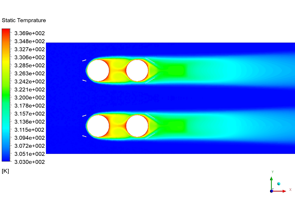
Examining the pressure contour shows that a pressure drop occurs in the flow path passing through the pipe. This pressure drop is due to surface friction. A sudden drop in pressure along the walls causes the flow to separate. We can see this separation in the form of a wake behind the pipes. The velocity vectors illustrate this well. From the temperature contour, it is clear that the airflow in the areas behind the pipe has a higher temperature than in other areas. It means that the Wake areas have low heat transfer. Since this research project aims to increase the heat transfer rate and reduce the heat exchanger volume, we can reduce the Wake areas.
The use of vortex generators is to create an obstacle in the flow path. Although this barrier, in turn, increases the pressure drop along the flow path, it allows us to redirect flows to areas in mind. The pressure drop is undesirable, but as seen in the velocity contour, the size of the wake areas behind the tube is significantly reduced. Instead, smaller wake areas are created behind the vortex generator. Reducing the wake area behind the pipe is of great value from the point of view of heat transfer. The vortex generator directs the flow to the space between the pipes, and on the other hand, the vortex generator reduces the flow passage in the channel.
Results & Discussions
Therefore, the vortex generator send the flow to the Wake areas at high acceleration. In addition to strongly affecting the Wake area, accelerated fluid flow brings a significant volume of cool fluid from the upstream areas to the Wake areas, resulting in better heat transfer and better mixing in this area, between the fluid in the upstream areas and the Wake areas. Besides, by injecting fluid in this area, we delay the separation of the pipe surfaces’ flow and it reduces the thermal boundary layer’s thickness.
Therefore, the vortex generator, as a passive technique to increase the heat transfer by narrowing the flow passage and reducing the wake area, and correcting the boundary layer near the walls, sends high-momentum fluid to this area. Slowly vortex generator, by reducing the passage of fluid flow behind each pipe also causes the flow through this section to hit the pipe’s outer surface with higher speed and shirt, which can be one of the influential factors in increasing heat transfer. We know that the higher the intensity of the fluid hitting the pipes, the higher the heat transfer rate from that surface.
You can obtain Geometry & Mesh file and a comprehensive Training Movie that presents how to solve the problem and extract all desired results.



دیدگاهها
هیچ دیدگاهی برای این محصول نوشته نشده است.